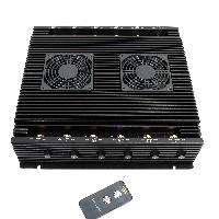
Cell phone signal jammer DIY

Posted by jammer
from the Food and Beverage category at
17 Jan 2024 02:45:10 am.
DIY Cell Phone Jammer - Components Required
| COMPONENT | COMPONENTUSAGE |
| Resistor R1 | Emitter Loading |
| Resistor R2 | Base Biasing |
| Capacitor C1 | Frequency Generation |
| Capacitor C2 | Feedback |
| Capacitor C3 | Feedback |
| Capacitor C4 | Noise Reduction |
| Capacitor C5 | Coupling |
| Capacitor C6 | Coupling |
| Capacitor C7 | Decoupling |
| Transistor Q1 | Amplification |
| Inductor L1 | Frequency Generation |
For any jammer circuit, there must be three important sub-circuits:
- Transistor Q1, along with capacitors C4, C5, and resistor R1, forms the RF amplifier circuit. This circuit is responsible for amplifying the signal generated by the tuned circuit. The amplified signal is then directed to the antenna via capacitor C6, which effectively blocks any DC current and permits only the AC component of the signal to be transmitted.
- Upon activation of transistor Q1, the collector's tuned circuit is also activated. Comprising of capacitor C1 and inductor L1, this circuit functions as a zero resistance oscillator, generating highly amplified frequencies with negligible damping.
- The magnetic charge flowing through the inductor diminishes, causing the capacitor to be charged with an opposing or reverse polarity. This cycle is repeated, and eventually, the inductor charges the capacitor until it reaches zero charge.
- The oscillation ceases once internal resistance emerges, marking the culmination of this ongoing process. Prior to reaching the collector terminal, the RF amplifier feed passes through capacitor C5, followed by C6. Capacitors C2 and C3 generate random pulses (noise) at the frequency produced by the tuned circuit.
- Tuned circuits are enhanced by RF amplifiers to amplify the frequencies they produce. The combined output of the tuned circuit's frequency and the noise signal from capacitors C2 and C3 is then amplified and transmitted.
Tags: signal jammer DIY
0 Comments


